


 |
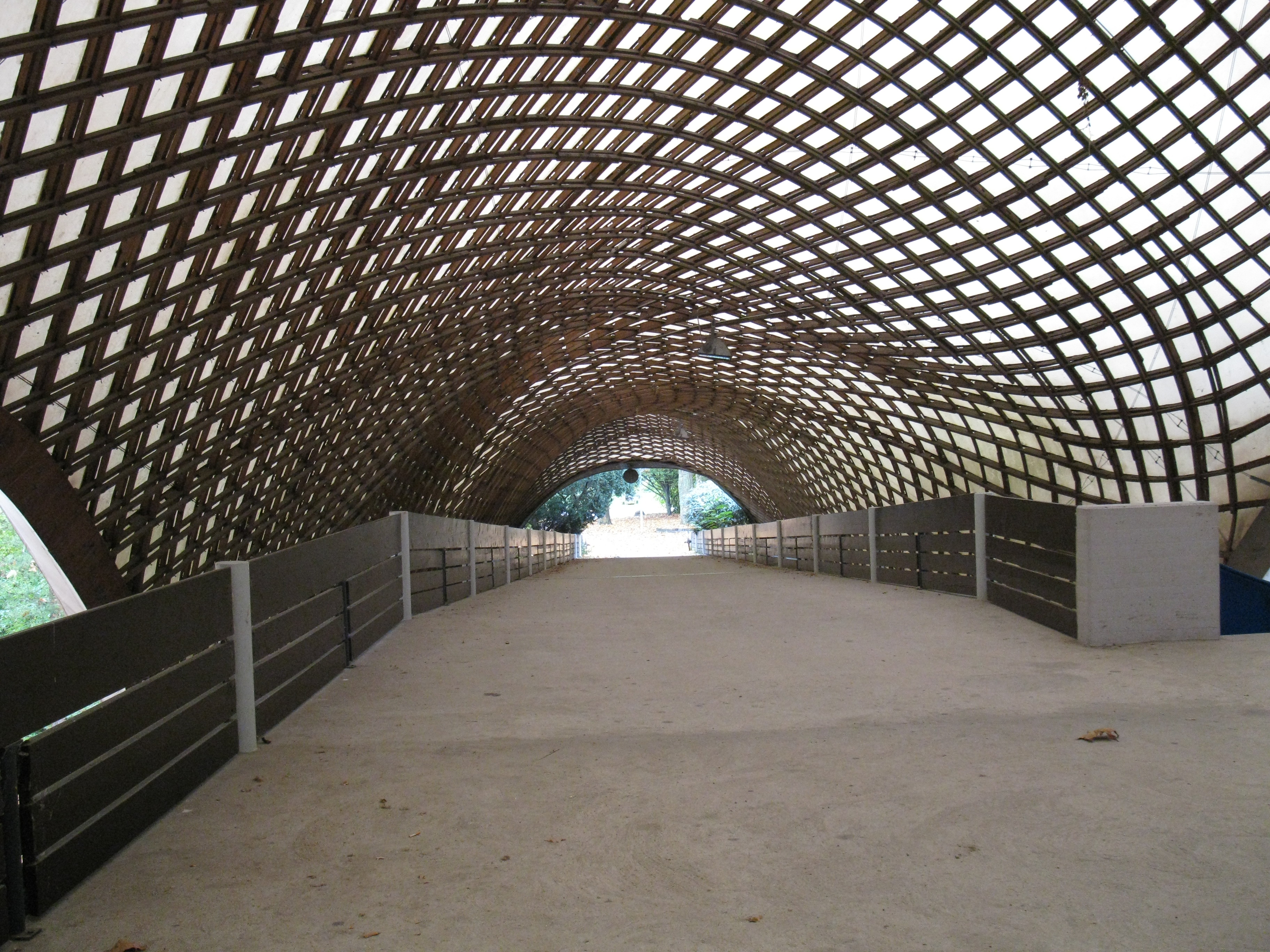
| Fig. 1:Interior of Mannheim Multihalle |
Mannheim Multihalle– Hanging Chain Model
Mannheim, Germany
1975
Span: 85m
Jarred Mihalik, Melody Tan, and Sekai Zengeza
A Pavilion for the Bundesgartenschau
“Exhibitions traditionally, because their buildings require to have dramatic impact and because they only need to have a limited life, have often been the place where new ideas are tried out. . .”
– E. Happold, Structural Engineer 1
The famous Crystal Palace is one such example: It's large plate glass windows astonished the world when it was debuted in 1851. Other examples include Maillart's Zementhalle, and the Lausanne hanging structure. 1 In 1975, the Mannheim Multihalle became another structure that realized a new, revolutionary idea in the form of a practical structure.
In 1975, the Mannheim Garden Pavilion (Figure 1) was constructed as part of the Mannheim Bundesgartenschau, which can be translated as "Federal Garden Exhibition." The Bundesgartenschau is a government sponsored horticultural show held every two years in a major city of West Germany. It started in 1951 as an exercise in park and urban planning in order to reinvigorate shattered post-war cities, and became very popular because of its celebration of colour and landscape in, at the time, a dull world. 2 At its most basic level, the Bundesgartenschau consists of a large, open park area redeveloped and landscaped in order to display new and unusual species of plants from various growers and nurseries around the country. However, the modern Bundesgartenschau also provides a place ideal for sports, concerts, and other special events, as well as general recreational areas for people of all ages. Thus, the Bundesgartenschau was, and still is, much more than a simple flower exhibition - it is a national attraction that draws over four million people from all over Germany. Although the cost to plan and hold a Bundesgartenschau was substantial at the time, the show was still widely sought after as a way to increase a city's reputation and also to renovate its public areas, similar to the modern day Olympics. 1
In 1970, the German city of Mannheim was chosen as the site for the 1975 Bundesgartenschau, and the planning for the event began immediately. There were two main sites that needed developing: the Luisenpark, located on the south side of the Necktar River, and the Herzogenriedpark, located on the north side of the river where the buildings for the show would be constructed. It was decided that a multipurpose event hall would be needed in the Herzogenriedpark and a design competition was held to see which idea would serve the city best for its moment in the spotlight. 3
A Multihalle in the Making
The winning architectural firm for the Herzogenriedpark was Carlfried Mutschler and Partners, which worked with landscape architect, Heinz H. Eckebrecht, to develop the master plan for the park area. Their design entailed centering the park around an "information axis" consisting of exhibitions, shops, kiosks, administrative offices, and more. At the center of this axis, and thus the center of the park, was to be the Mannheim Multihalle, a light and airy conjoined multipurpose hall and restaurant that would aesthetically harmonize with the hilly landscape of flowers and trees. The multipurpose hall itself was planned to be a structure suitable for not only for the Federal Garden Show in 1975, but also for radio/television shows, festivals, lectures, games and sporting events, political/trade union assemblies, and other large exhibitions that could be held after the event.
During the design phase of the Mannheim Multihalle, several different building types were proposed by the firm. The first design consisted of large umbrellas arranged in a straight line, suspended on inflated gas-filled balloons. The idea was not carried out, however, due to the sensitivity of both the balloons and umbrellas to wind loads. Other pneumatic designs were also investigated, but were abandoned for reasons of high material cost and production. The designers then turned to tent structures, still hoping to achieve an airy form serving as a continuation of the surrounding hilly landscape, but again decided against such a design. Thus, they asked Professor of Architecture, Frei Otto, to assist in the design of the project. 4
Frei Otto was a noted architect of the time who already had experience working on the structures of the 1955 Bundesgartenschau, held in the city of Kassel. He also had experience creating gridshells for the Montreal Pavilion for Expo '67. After studying and teaching in the United States for a short time, Otto returned to Germany to start his private practice and further develop his studies of lightweight membrane structures.5
After input from Otto and further deliberation, an agreement was reached that a lattice gridshell structure would be the best design for achieving the open, airy nature they desired, while also fulfilling the structural purpose of the multipurpose hall. The final design consisted of two separate domes: one would house the multipurpose hall, while the other would house the restaurant. These two domes would be joined by an elevated walkway covered with the same type of membrane that would stretch over the domes. This membrane was made of polyvinylchloride (PVC) reinforced with open-meshed polyester fabric.6 Timber was used for the lattice gridshell for both structural and aesthetic reasons. Aesthetically, it was light and fit with the theme of a garden show. Structurally, it was stiff enough to resist buckling but flexible enough to deflect in order to form a strained lattice gridshell. These choices of materials will be discussed more later on.
Once these decisions were made, the laborious process of preparing detailed plans and calculations along with choosing the final structural form followed. The timber lattice gridshell formwork was an innovative idea, but one still rare in practice. Thus, very little was known about the structural behavior of these shells, and how that behavior would affect the materials used in the project. The original structural engineers contracted for the Mannheim Multihalle resigned after stating that the structural calculations were too difficult. The clients then hired Ove Arup and Partners (the forefather of Arup Engineering) to make the calculations involving the weight and shape of the multihalle. Other important contributors to the Mannheim Multihalle's construction and design included Dr. Ewald Bubner (an experienced consultant in the form finding of gridshells and a partner of Frei Otto), structural engineers Edmund "Ted" Happold, and Ian Liddell, and general contractor Wilhelm Poppensiecker.7
What is a Gridshell?
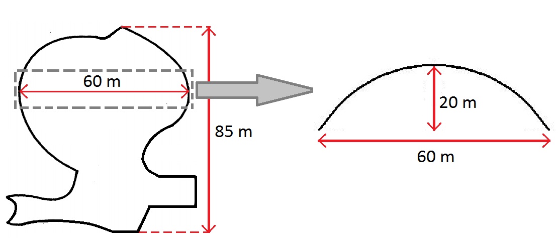
Put simply, a gridshell is a structure made of individual elements that form a regular grid spanning the area the structure covers. A gridshell is but one form of a shell structure, which can also be made from concrete and steel. Their efficiency and thinness come from the fact that they derive their strength from their geometric shape.8 Shells can have multiple layers and different ways of joining materials at nodes. However, common to all these forms is a thickness that is extremely small compared to the overall dimensions of the structure. For example, the Mannheim Multihalle spans 85 meters (Figure 2) and contains 7400 m2 of roof area, but its shell thickness is less than half a meter.9
 |
| Fig. 2: Multihalle Dimensions |
Throughout history, shells have been less popular than the typical simplistic construction technique of combining horizontal (slabs) and vertical elements (columns). This is most likely due to the fact that these structures remain difficult to design and analyze, even with advanced computational analysis. However, timber gridshells, like all shells, resist loadings through tension, compression, and shear forces (resisted by node joints with disc springs), all in the plane of the shell.1 This means that the shell section can be very efficient in the use of materials.
Physical Modeling of the Multihalle
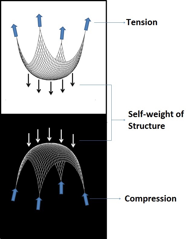
When the Mannheim Multihalle was being developed, computational analysis was still in its infancy. Many engineers and architects of the time still relied at least in part on physical models to give an approximate rendering of the forces that would act on the real world structure. Physical models also helped to show where the members and nodes of the gridshell should be located in order to develop a structurally sound building. In essence, a small model of the building would show where the placement of the wooden lathes and building borders would fall. These placements could be scaled up to approximate where the materials should be placed during the actual construction of the building. Thus, the decision was made to build a scale "hanging chain" model of the Mannheim Multihalle in order to find the projected form of the gridshell.
 |
| Fig. 3: Forces in Hanging Chain and Inverted Structure |
The model was produced as a joint venture between Mutschler & Partners (the architectural firm) and Atelier Warmbronn (Frei Otto's company). A small suspended chain model of the projected structure was created at a scale of 1:500 at Otto's workshop in Warmbronn, Germany.6 Using lengths of wire thread that were spread evenly over the surface area of the model, the approximate length and width of the gridshell was found. These threads represented the wooden lathes that would form the gridshell in the final structure. In all, the suspended net worked as a good model for the Mannheim Multihalle because it was put under entirely tensile forces from its self weight. (In reality, the self weight of the structure is negligible compared to the forces of wind and snow, which constitute the primary loads for such large shell structures. Thus a form chosen by using self weight as the primary determinant will not be perfect, but is still a viable and simpler solution.) When a uniform distributed load is applied to a suspended line, it naturally shapes itself so as to be free of bending moments. In other words, all loads are transmitted by axial forces. Thus, in a hanging chain model, the chains remain fully in tension. Once the form is inverted (flipped upside down), all the internal forces act in compression (Figure 3).11 This is important because the wooden lathes in the gridshell can resist axial forces well (forces that act along the axis of the beam) but are poor at resisting shear forces (forces that act perpendicularly to the beam).
Because the hanging chain model was too small to include every single grid and node of the proposed structure, the engineers had to develop a system which would scale up to actual size well. They decided to represent every third mesh of the structure on the model, meaning one thread on the model would represent three wooden lathes on the actual structure.6 The wire mesh was created using surprisingly simple materials: it consisted only of a wire rod with hooks at both ends approximately 15 millimeters in length, and a wire ring approximately 2.5 millimeters in diameter. While the wire represented the timber beams of the gridshell , the rings represented the nodal joints. This arrangement of chain elements allowed the production of a mesh of any size, and also ensured that the angles could be freely displaced. This angular freedom provides the possibility to produce either a curved or planar form using this quadrangular equal-meshed net. Once the net was completed to the approximate proportions, it was suspended on a final framework which consisted of brass support columns, plexiglass, and brass wire boundaries. The edge lengths were then adjusted to fix any minor inconsistencies in the form of the smooth domes. The next step was using the model to realize the fully formed structure.
Scaling the Model to the Actual Structure
When the model was finished, Professor Klaus Linkwitz and his team for Applied Geodesy at the University of Stuttgart used stereophotogrammetry to measure the model. Stereophotogrammetry is a technique which involves estimating the three-dimensional coordinates of points on an object by using measurements made in two or more photographic images taken from different positions. From the photographs, the three dimensional object can be reconstructed using laws on reproduction of the central perspective. Thus, the locations for every node to be placed in the structure were found, as well as the necessary lengths for the wooden laths.6 These dimensions were also essential to create the boundary of the shell and predict how it would eventually behave.
However, the form-finding process was not yet complete. Though the making of the model was attempted to be as precise as possible, it was still not exact enough due to errors during the mechanical building of the mesh net and also possible measurement errors. Thus, a technique known as the force density method was used to further verify the results found from the physical model.4 This was done by taking the coordinates obtained using stereophotogrammetry and inputting them as data into a computer model. This also allowed the curvature of the projected structure to be smoothed out. Once all the data were in the computer, other minor adjustments could be made: members were set to be of a single length, and the forces in the structure was checked to be in equilibrium.3
Construction of the Mannheim
One of the most interesting and unique aspects of the Mannheim gridshell was its construction process, which is much quicker and cheaper than the methods used for other buildings. The grid starts off laid out in a flat position. In the case of the Multihalle, a double layer grid was actually used (Figure 4). This was due to the architect's prior decision that the size of the wooden beams be no greater than 50 mm by 50 mm, for aesthetic reasons.6 Since this size would not support the intended span, the engineers decided to use a double layer grid, increasing the stiffness of the completed structure (by making the wooden grid harder to change form) without too much additional cost or changes to its construction method, since such little material is used for one layer of the gridshell.
 |
| Fig. 4: Detailed View of Double Layer Grid Shell Node |
Within this double layer grid, there are over 33,000 joints in the Mannheim Multihalle, which makes it clear that the node design of the structure was also important for it to be a success. Since the Mannheim Multihalle is double layer grid, each node has a total of four laths crossing at a single point. In addition, the joint must be able to freely rotate: this is imperative for the gridshell to be able to assume its final form as it is raised from the ground, just as the hanging chain model was free to assume its own hanging form. While single holes were drilled in the inner two beams, longer slots were drilled in the outer two beams to ensure that the layers had some space to move relative to one another during construction (due to the bolts being able to slide).4
Once the gridshell was in place, a system had to be devised to raise it to its proper position. The first method suggested was to use cranes to pull up sections of the shell and then fix them using the nodes and boundary conditions. However, this was deemed to be too expensive as the cranes would have to be onsite for an extended period of time. The second, more practical, method involved a mixture of pushing upward on the shell from below and pushing inward on the sides. The upward method used support towers to lift up small sections of the shell (which was still flexible during the construction phase due to the slotted bolts at the joints that enabled relative movement between layers). The inward method simply involved using jacks to push gradually inward at the boundary of the Multihalle, raising it up into a fixed position.3
Construction of the building began in 1973 and was finished on time within a year. Once the shell was in the correct position, the node joints were tightened and wooden shear blocks were inserted into the angles between the lathes to ensure they would not displace further. These shear blocks also helped resist the bending moments due to load combinations of wind and snow. Once the boundaries had been fixed, the Mannheim Multihalle was complete.
Materials, Cost, and More
 |
| Fig. 5: Bracing Cables that Help to Prevent Buckling |
The cost of the multipurpose hall was relatively low compared to other typical building projects at the time, with only 6 million DeutschMarks (DM) budgeted for its construction (a townhall constructed at the same time could cost up to 30 million DM). 6 million DM in 1973 is equivalent to approximately $80.5 million in present-day US dollars. The completed roof structure covers an area of 7400 m2 while weighing only 16 kg/m, and costs roughly 400 DM/m2. Hemlock was used for the timber laths, which were 50 mm by 50 mm in area. The largest span of the Multihalle was 85 meters, while the secondary span was 60 meters. In addition, bracing had to be added for buckling reasons - this consisted of twin 6 mm cables placed at every sixth node (Figure 5).3 This bracing also helped resist the forces of "disturbing" loads, or loads other than the dead weight (i.e. snow and wind)4. Without this bracing, the beams in the structure would be susceptible to sudden failure.
The Significance of the Multihalle
The Mannheim Multihalle is a structure created simultaneously from mathematical investigation (theoretical applications) as well as form finding (practical applications). Having a physical model present allowed the designers to correctly create the form: precise camera imaging combined with detailed measurements enabled a successful scaling from the model into the full size structure. Throughout the design process, these two approaches worked in harmony, resulting in a form that reflects its interwoven ideals. The Multihalle clearly demonstrates the principle that tensile forces in a chain net flip to compressive forces in a shell structure when the orientation is reversed through the thinness it was able to achieve for such large spans. It is also a prototype of a construction method that was both simple and economical. The idea behind the structure was revolutionary for its time in the 1970's and continues to serve as an inspiration today.
The Mannheim Shell Today
Today the Multihalle stands in monolithic silence, after a long period of openness and versatility. Originally designed to have a mere two year lifespan, the structure was received well by the public and was left standing until the present day. In this time, it served as a space for both public and private functions, proving that the shell structure is a design that can have a multitude of uses.
Due to concerns about safety, the central dome structure is not currently open to the general public. This is mainly due to the problems with the integrity of the wood (designed for a much shorter lifespan) and also increased modern safety standards.4 Thus although the building is currently closed, one can only hope that the German government sees fit to restore and renovate the building to its former glory as a pioneering piece of structural art. In the meantime, the curious visitor can eat at the adjoining restaurant (covered by an extension of the same grid shell) and observe Koi fish and ducks swimming in the placid ponds outside.
Influences on Today’s Shells
Even though the Mannheim Multihalle was built in the twilight of the shell construction period, its lightweight timber construction and complex shape sets it apart. It could be argued that this shell has provided the inspiration for later, modern gridshells in places as diverse as England (the Downland Gridshell designed by British architectural practice, Edward Cullinan Architects in 2002)12 and Japan (Japan Pavilion for the Hanover Expo designed by architect Shigeru Ban in 2000)3 in both form and aesthetics. The Mannheim Multihalle was physical proof that little more than simple math and a detailed model could be used to create a structure with both organic materials and form.
 |
| Fig. 6: Princeton University CEE 463 Visit to the Mannheim Multihalle |
1. Happold, E., and W. I. Liddell. “Timber Lattice Roof for the Mannheim Bundesgartenschau.”The Structural Engineer 54.7 (1976): 247-57.
2. Sheard, P. (2011). Blumen marvellous. Architects' Journal, 233(26), 42-45. 3. Paoli, Celine. (2007) “Past and Future of Grid Shell Structures.” (Master’s thesis). Massachusetts Institute of Technology, Boston, Massachusetts.
4. Harris, R., Dickson, M. and Kelly, O., 2004. “The Use of Timber Gridshells for Long Span Structures.” In: 8th International Conference on Timber Engineering, 2004-01-01.
5. Roland, Conrad. “Frei Otto: Structures.” Spottiswoode, U.K., 1970.
6. Burkhardt, Berthold, and Frei Otto. “IL 13: Multihalle Mannheim. Stuttgart: Freunde und Förderer der Leichtbauforschung, 1978.”
7. “Mannheim Multihalle” Structurae, http://en.structurae.de/structures/data/index.cfm?id=s0000691
8. Niordson, Frithiof. “Shell Theory.” North Holland, Netherlands. Elsevier Science Publishers, 1985.
9. Adriaenssens, S., Harris, R. et al. “Dynamic Relaxation with bar and beam elements.” 2011.
10. Sanders, F. (2007) "Is the Earth's crust proportionately thicker than an eggshell?" http://franksanders.com/FrankSanders/Frankster's%20Blog/20A8FEC4-34B4-4956-88A5-4B1C37105A4E.html 11. Schenk, Mark. “On the shape of Cables, Arches, Vaults and Thin Shells.” 2009.
12. Jensen, Frank. “The Downland Grid Shell.” Model Analysis Award: Winning entry. 2000.