


 |
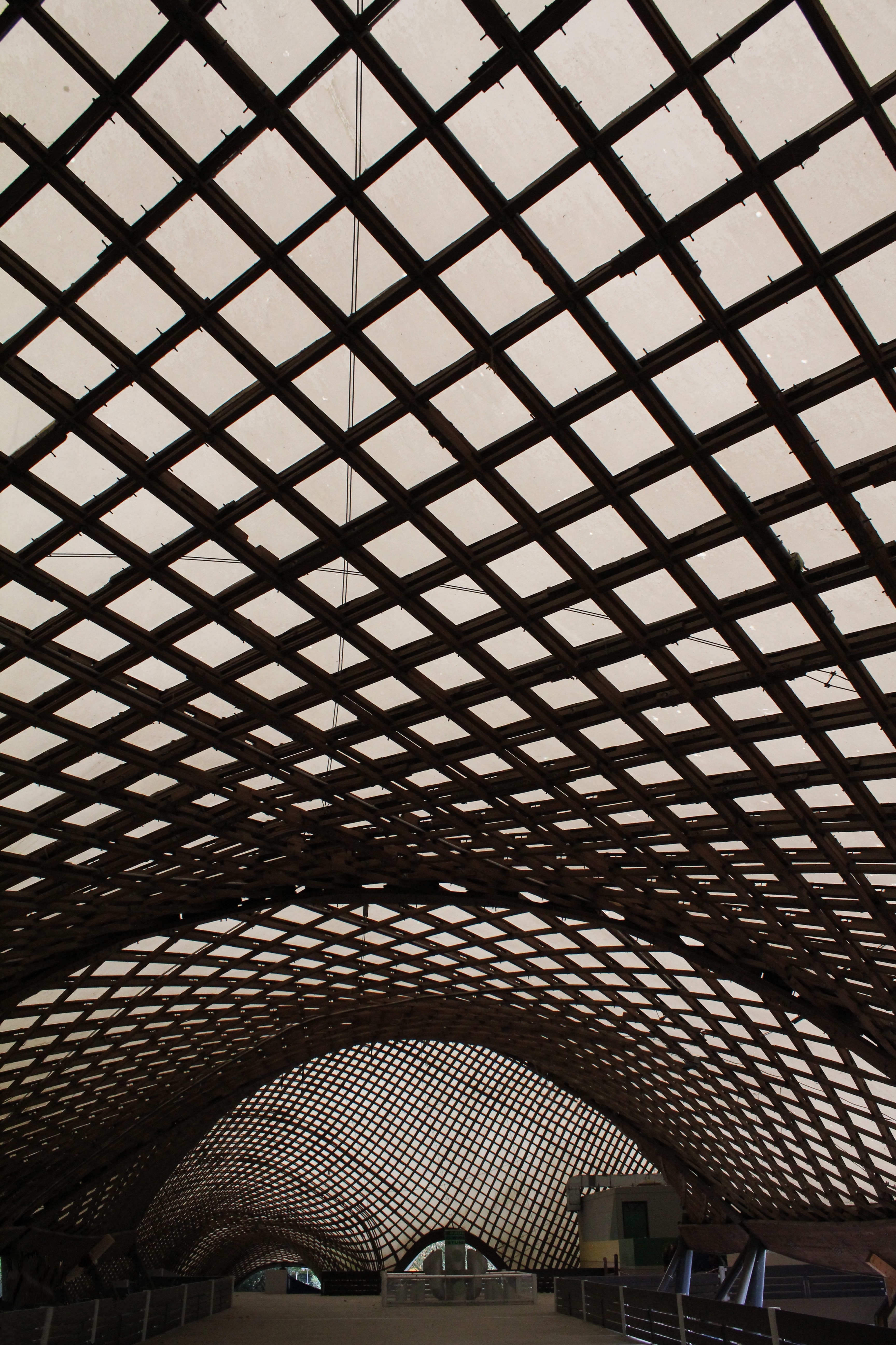
| Figure 1: The Mannheim Pavilion |
Mannheim Multihalle
Mannheim, Germany
1974
Span: 60m x 60m
Frei Otto and Architects Carlfried Mutschler and Winfried Langner
Revival of a City
Mannheim was once one of Germany's greatest industrial centers. It was a place of burgeoning creativity, where amongst many innovations Karl Drais invented the first bicycle, and Carl Benz patented the first gas-powered automobile [1]. The prominence of industry in Mannheim naturally led to the city's importance in both WWI and WWII, eventually becoming one of Nazi Germany's key industrial centers. As a result of its role in manufacturing, Mannheim was also seen as a main target for Allied forces, and air raids on the city began in December 1940. The bombings lasted until the end of the war, devastating the city and leaving half of it in ruins [2].
The extent of damage done to Mannheim during WWII made post-war reconstruction a slow process. It was during this reconstruction phase of the city that the Mannheim Pavilion was eventually envisaged and realized. The Mannheim Pavilion, shown in Figure 1, was the result of a contest held to host Germany's Bundesgartenschau, a federal biennial horticulture show that funds the transformation of an open area - usually a rundown location - within the host city into a garden exhibition. Winning the bid to host the 1975 Bundesgartenschau was not only an honor for Mannheim, but it also had other important implications for the city. Part of the excitement created by the construction of the exhibition is the accompanying redevelopment of the area surrounding the venue, including "gardens of every kind, paths, lighting, lakes, kiosks and restaurants" [3]. For Mannheim, this show meant that an entire area of the city would be redeveloped, which was crucial for aiding in its reconstruction process. It was decided that the exhibition would be located in Mannheim's Herzogenried Park, and various architects were asked to submit designs for the exhibition. Architects Carlfried Mutschler and Winfried Langner, also from the firm of Carlfried Mutschler & Partners of Mannheim, created the winning design in 1971, and landscape architect Heinz Eckebrecht was chosen to design the gardens surrounding the exhibition space. According to Langner, their design concept focused on "a light, airy construction to harmonize with the landscape of flowers, trees and artificial hills" [4]. The perplexing final shape of the Mannheim Pavilion seems less strange in light of the architectural aim of attaining natural harmony by making "two kinds of artificial hill - one of earth, one of grid shell." With a budget of only 6 million DM (Deutsche Mark, the West German currency at the time) - equivalent to approximately 4 million USD today - the lightweight structure would also reduce the overall cost of the project and keep the structure within the budget [4].
The architects originally conceived of various designs for the pavilion before arriving at the final grid shell concept, the first of which was to create a roof over the exhibition space out of large umbrellas suspended on helium balloons, an idea which the planning authorities rejected [4]. The architects next began thinking about different tent constructions that could accomplish what they were envisioning, and they brought their design to a famous roof architect named Frei Otto for advice, and decided upon a grid shell design after Otto agreed to serve as a consulting engineer for the project and its construction. Otto had several previous experiences with erecting grid shells, though these were on a much smaller scale than Mannheim. These include the Essen Shell, a smaller shell in Berkeley, California, the Montreal pavilion for the Expo in 1967, as well as a few other projects [4]. The final pavilion design required a free-form roof covering three separate spaces, with the main hall (called the Multihalle) spanning 60m by 60m. Edmund Happold and Ian Liddell, both from the firm Ove Arup & Partners, were the primary engineers hired for the project, and other consultants also provided input on the final design and construction of the shell.
Construction for the pavilion began in December 1973, and the lattice was gradually erected throughout April and June of the following year. The Mannheim Pavilion was successfully erected by November 1974, and the garden exhibition opened to the public on April 18, 1975 [5].
Forces and Form
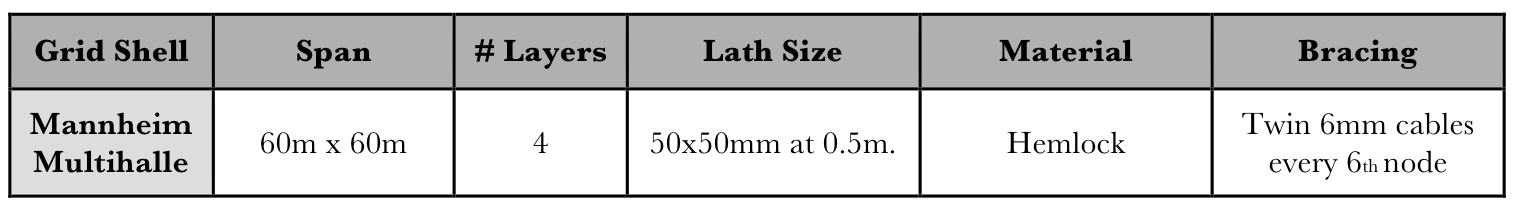 |
| Table 1: Dimensions of the Mannheim Multihalle, the pavilion's main hall [6] |
 |
| Figure 2: Diagram of the Multihalle's dimensions |
The form finding process of the Mannheim Pavilion involved a hanging chain model. This method allowed architects to develop architectural spaces that fit any plan giving a "sensible structure" [4]. Frei Otto had already used this technique to derive his first timber grid shell in Deubau by suspending threads loaded with nails, and he refined his technique by using a chain and its self-weight for the Mannheim design [7]. These models were effective in creating pure tension shapes, that when inverted, created pure compression shell results. The curvature found in the hung quadrangular chain net meant that there was no in-plane shear stress in the lattice that replicated that same shape.The design of the Mannheim Pavilion (shown in Figure 2) involved a computer generated mathematical model as well as the physical one, which in the end yielded very similar results to what they had found in the hanging chain model. The computer model was an idealization, and to some extent a simplification, of the actual model due to its complex four-layer grid and unique construction process involving scaffolding to manually erect the shell from below. The idealized model represented the shell using fewer members and made assumptions about joint flexibility.
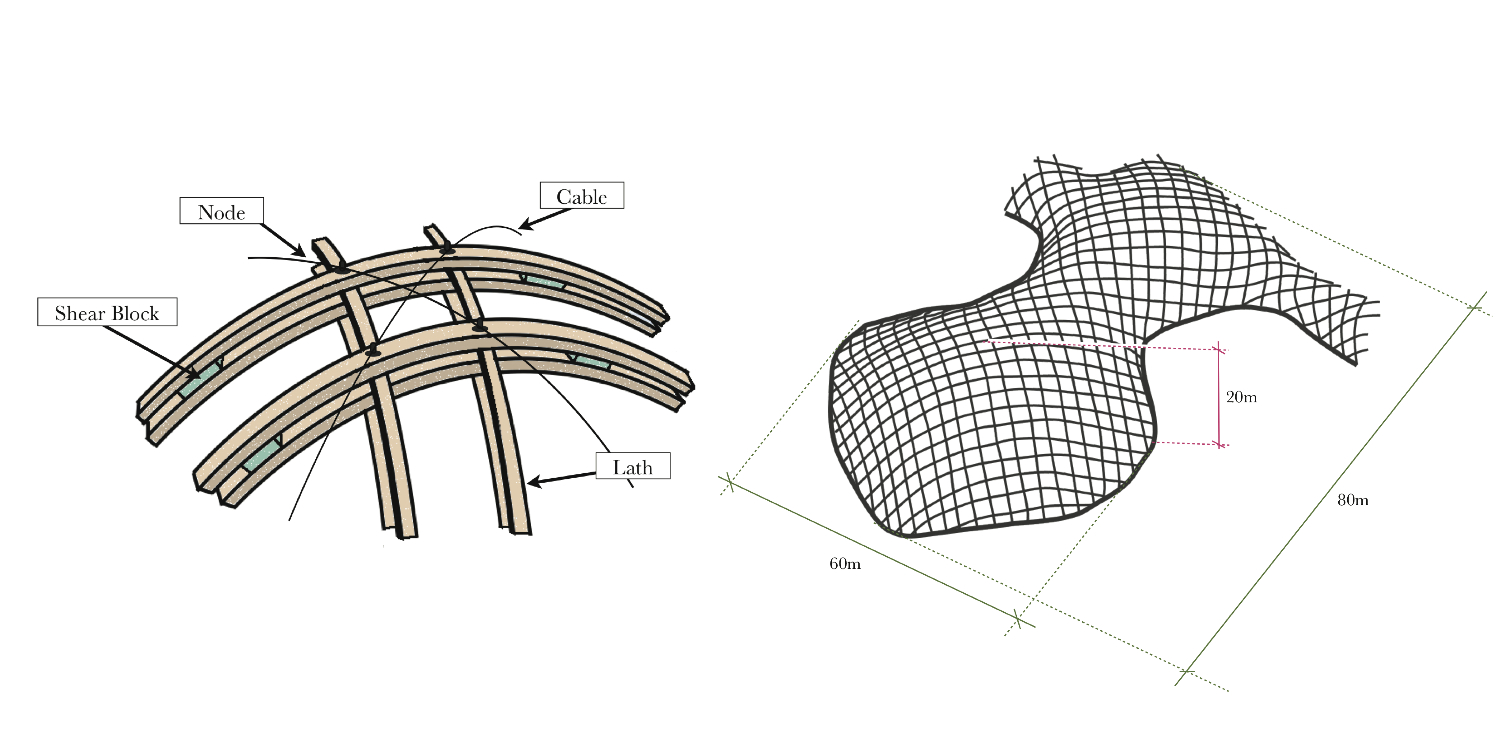
The term lattice shell, also known as grid shell, refers to a "doubly curved surface formed from a lattice of timber laths bolted together at uniform spacing in two directions" [3]. The grid is initially flat and held together by pinned joints that allow parallel movements between laths, as shown in Figure 3. This is a mechanism with only one degree of freedom. When the structure is erected into its doubly-curved shape, the forces would transform the square grids into similar parallelograms causing the diagonal lines through the nodes to change. Figure 4 demonstrates how the forces are taken by a grid shell system. The double curvature of the design gives the membrane strength and stiffness [5].
 |
| Figure 3: Lattice Distortions |
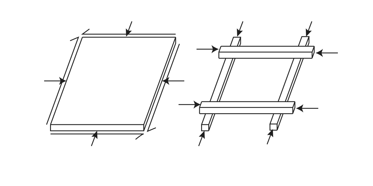 |
| Figure 4: Continuous shell and lattice shell elements: the continuous shell can resist normal and shear forces while the lattice shell can only resist forces in the direction of the lath |
The chosen grid shell roof system required detailed planning and engineering due to the complexity of the structural system. There are a number of factors that affect the span and shape of grid shells, the main two being the stiffness and minimum radius of curvature of the wooden laths [8]. In the first case, the grid must be stiff enough to resist the buckling of the shell. The laths must also be able to bend enough to achieve the required radius without breaking. Another factor that must be considered in the design process is the construction feasibility, since the softer the flat unstiffened grid is, the larger the number of support points needed during the erection of the grid [4]. The grid shell structure allows for an extremely small thickness to span ratio. The thickness is determined by the stiffness needed to withstand buckling and asymmetrical loading. Frei Otto chose western hemlock wood for the construction of the Mannheim Pavilion because it was available in the long lengths needed to allow for a feasible construction. The hemlock tree reaches a height of up to 60m and is native to the west coast of America [3].
One of the requirements of the architects was that the cross-section of the laths be 50mm x 50mm. At first, the designers considered a single-layered grid shell. After several model tests, Happold and Liddell realized that a single layer of this lath size would cause the collapse load to be too small if they wanted to span such large lengths. Since increasing the lath size would not only displease the architects but also increase the initial bending stress, the engineers decided to double the laths one above the other creating four - rather than two - layers of wooden laths (see Figure 5)
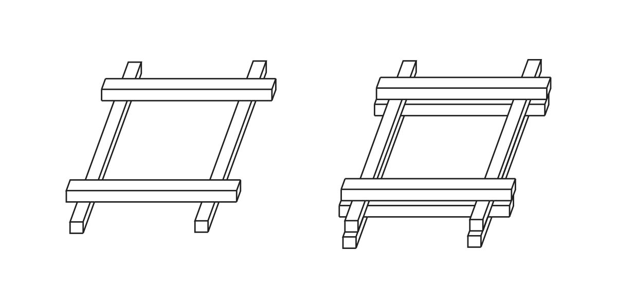 |
| Figure 5: The doubling of the layers of the lattice grid shell, used for increased stiffness |
The loading patterns on a shell can be divided into funicular and disturbing loads. The former refers to the self-weight of the structure or any kind of uniform loading. Disturbing loads include wind loads and other asymmetrical load scenarios that create large deflections [8]. The wooden laths transfer the loading to the perimeter of the grid, and since an extra layer of grid had been added, there was also an added eccentricity that caused an increased moment around these members. The irregularity of the shape of the Mannheim and the asymmetrical loading also meant that cable ties were needed to increase the diagonal stiffness of the structure.
There are two types of lattice shells: the unstrained and the strained lattice shell. The difference between the Mannheim shell (strained) and unstrained shells is that initially, the unstrained shells are made of pre-bent members. Therefore, the already curved members experience no strain during the erection process.
With four layers of wooden laths to join, the connection system in the Mannheim Pavilion was extremely complex. The joint had to allow the members to rotate during the erection process, creating the parallelograms that form the structure's organic shape. They also had to accommodate for the sliding between the two parallel laths running along each grid that would happen during the construction process. For this, a pinned connection was needed between the middle two laths and slotted holes were needed in the outer layers to allow for this movement [6], as shown in Figure 6. Once the final shape was achieved, the laths had to be prevented from slipping. In the Mannheim Pavilion this was done by bolting the pin joints after the grid shell was in place.
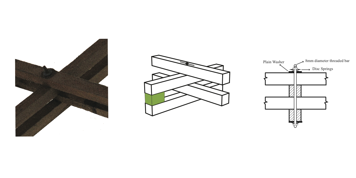 |
| Figure 6: Mannheim joints system |
From Flat to Curved
The hanging chain model relates to the final shape of the shell. However, the model is different than the timber shell in that the curved laths from the finished structure have bending in them, while the chains from the model do not. This phenomenon occurs because during its erection, the grid is pushed up from below using scaffolding towers, which induce bending stresses in the laths. After the mesh is lifted into shape, the boundaries must be fixed (see Figure 7). The pins that once allowed for free rotation of the nodes must also be tightened with node bolts.
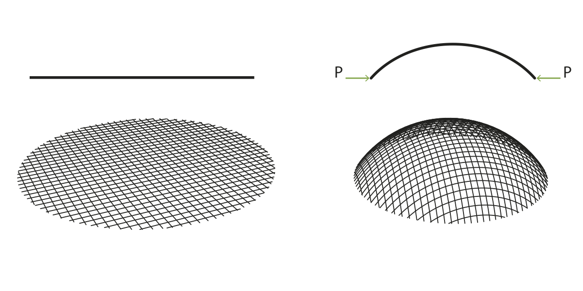 |
| Figure 7: From flat to curved: the forces along the boundary cause the wooden laths to bend into a curved shape |
The double grid requires the tightening of the bolts in order for the parallel layers to work compositely, therefore increasing the stiffness of the shell. The computer model showed that even after the tightening of the bolts, it was necessary to further increase the stiffness in members under bending and related shear stresses [4]. This led to the addition of blocking pieces, also known as shear blocks, between parallel laths throughout the shell. These shear blocks serve to increase the total moment of inertia of the two connected laths, thereby increasing the shell's overall stiffness.
Although the out of plane shear stiffness was provided by bolting and shear blocks, steel cable ties were needed to provide the diagonal stiffness to the shell. Figure 8a shows how these cables run through the diagonals of the grids, and are connected at every sixth node. These cables have a 6mm diameter and are stressed by inserting a small block of wood or steel between two parallel cables, as shown in Figure 8b.
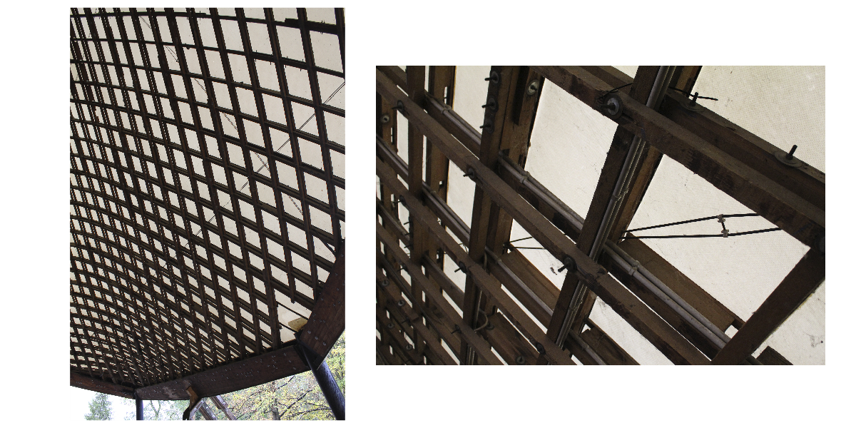 |
| Figure 8a (left): The cable ties provide the in-plane shear stiffness to the shell |
| Figure 8b (right): Inserts between parallel cables increase tension |
The forces flow down to the boundary of the mesh, where the structure had "almost every conceivable type of edge detail, perhaps too many" [4]. The Mannheim Pavilion's perimeter is composed of four different boundary types: arches, concrete, laminated timber beams and cable boundaries, with concrete being the most often used [9]. In the concrete boundary, the laths are connected with bolts to a wooden board that is set at the correct angle, as shown in Figure 9. It was decided that each metal angle should be fabricated separately because this was the cheapest solution to the varying angles at which the mesh met the ground. The boards were then connected to concrete blocks using steel brackets. The boundaries at locations where there are openings were either arches or laminated timber beams. The timber beams provide the necessary resistance to the lath force without increasing edge thickness, which are often connected to columns.
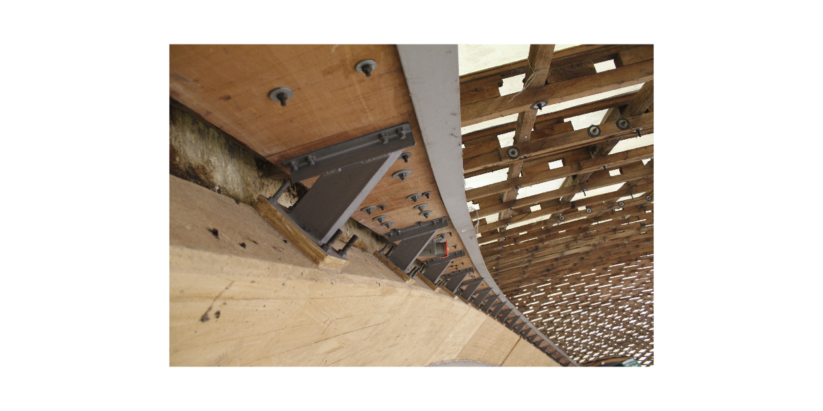 |
| Figure 9: Concrete ring beam |
Structural Analysis
To understand the forces and stresses acting on the Mannheim Pavilion, a simplified structural analysis was performed. Since the grid lattice of the Mannheim Pavilion was erected from a flat grid to a curved shell, two forces need to be considered: the initial force (Pinitial) required to begin deflecting a lath, and the subsequent force (P) required to keep the lath deflected once it is in place, to be referred to as the "lift force." These two forces were determined (without considering the lath's self-weight) using Timoshenko's elastic stability theory [10], represented by the arrows in Figure 10.
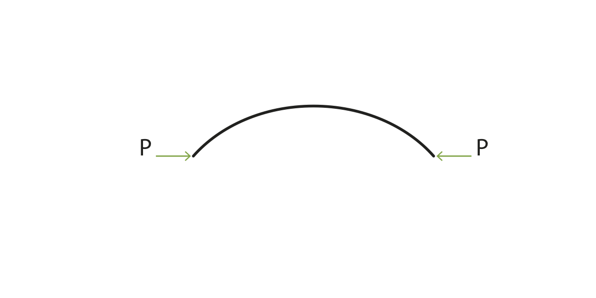 |
| Figure 10: Force needed to maintain bent shape of lath |
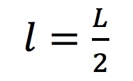
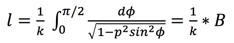
Since the elastic stability theory deals with a cantilevered beam, only half the arc length of the Multihalle was considered. Therefore, l is defined in Equation 1 as:
 |
(1) |
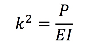
where L = 80m, and l = 40m. Given this value of l and angle of deflection α of 60 degrees for the Multihalle (based on the arc length and the Multihalle's estimated height of 20 m), the elastic stability theory allows for an estimation of the elliptic integral B that can be used to solve for the lift force P. For the dimensions of the Multihalle, B = 1.686. Using B, k can be solved by substituting Equation 3 into Equation 2:
 |
(2) |
 |
(3) |
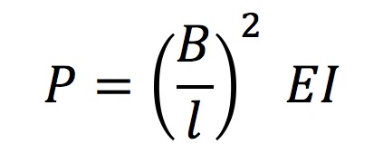
which, when combined, yield Equation 4 to solve for the lift force P:
 |
(4) |
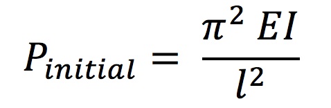
The initial force Pinitial can be solved using Equation 5:
 |
(5) |
The initial force required to deflect a lath (Pinitial) and the lift force P required for maintaining the erected shape were investigated for several materials, including wood, steel, and aluminum. To better understand these forces, two scenarios were considered for each material: (a) one lath with a cross-section of 50mm x 50mm working independently and (b) two such laths connected by a shear block and forced to act compositely, although they are separated by a distance of 50 mm due to the shear block. The difference in values of Pinitial and P for laths made of the various materials is a direct result of differences in their material properties, namely their Young's Modulus. Table 2 shows the variation in Pinitial required to lift and P required to maintain (a) a single lath and (b) two connected laths working compositely for each material:
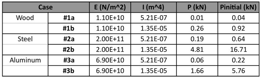 |
| Table 2: Variation in P and Pinitial based on material and moment of inertia |
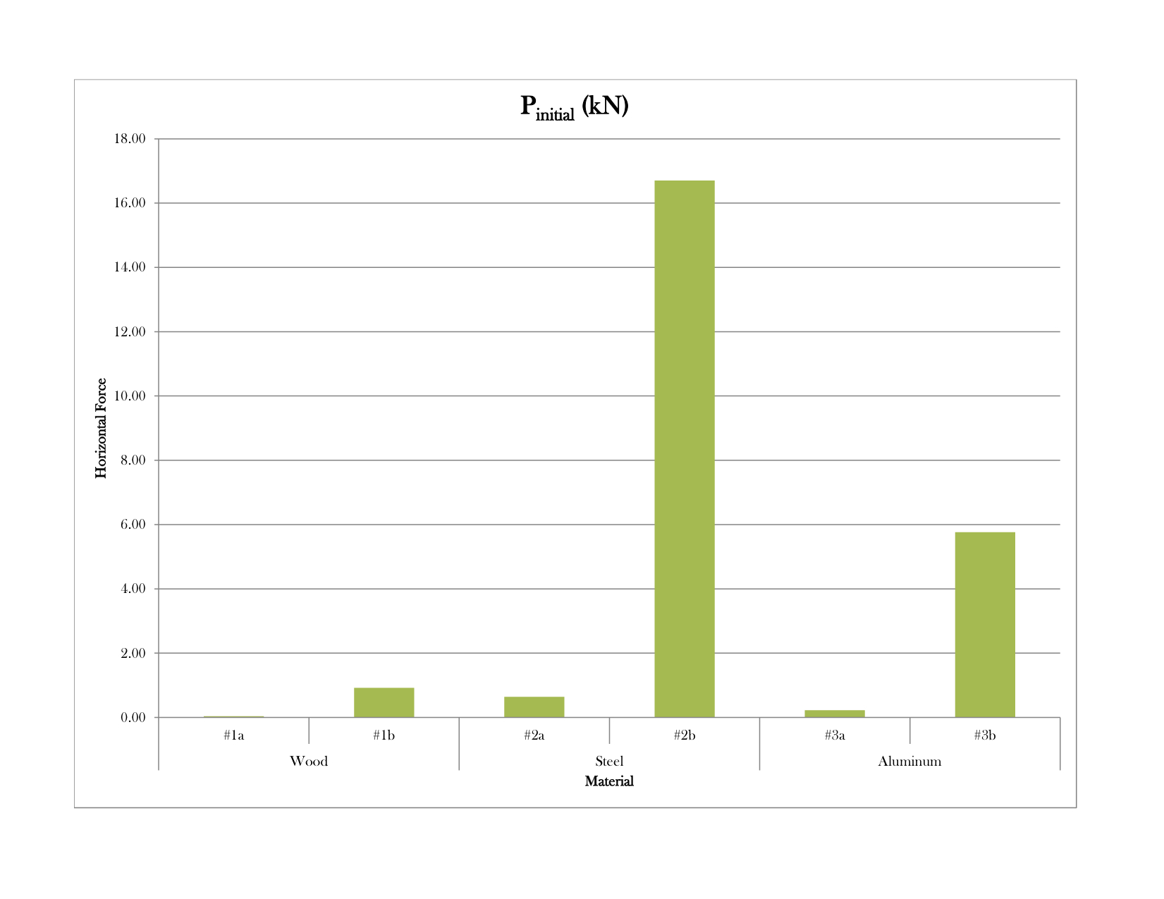 |
| Graph 1: Initial horizontal force needed to lift the center of the lath |
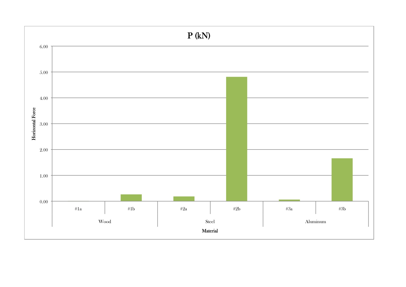 |
| Graph 2: Lift force needed to maintain the shape of the lath |
Graph 1 shows how the initial force differs from material to material in each of the cases illustrated in Table 2, and Graph 2 shows the differences in lift force required for each material. It is no surprise that steel requires - by far - the greatest amount of force, since it has the largest Young's Modulus (E). Materials with a large Young's Modulus, such as steel (E = 210 GPa), are stiffer and require a greater Pinitial and P because more force is needed to bend them. Materials with a smaller Young's Modulus, such as wood (E~10 GPa) and aluminum (E = 69 GPa), are more flexible and require a smaller Pinitial and P because they bend more easily. It is important to note the significant increase in initial force, Pinitial, that occurs if the shear blocks are introduced before erection. For wood, for example, the initial force increases from 0.04 kN to 0.92 kN if the shear blocks are placed prior to erection, which is a significant difference. Introducing the shear blocks later in the construction process (as was done in the actual construction of the Mannheim Pavilion), rather than prior to erection, results in an initial force only twice as large as Pinitial, and a lift force only twice as large as P, since the force required is that for lifting two individual laths rather than two connected ones. These values confirm the ingenuity of the erection process used to construct the Mannheim Pavilion, since the process reduced the overall lift force required without sacrificing the shell's final stiffness.
Once these forces were determined, the structural analysis program SAP2000 was then used to calculate the normal stresses experienced by the shell under four different load cases. These four loads include:
The lift force required to erect the shell latticeThe self-weight of the lattice
The design snow load
The design wind load
The equation used to calculate the stress of the laths in the first and second load cases is the following:
 |
(6) |
where Ia is the moment of inertia of a single lath, since these load cases are resisted by individual laths before they become connected via shear blocks, and ya is equal to 0.25m (perpendicular distance from the edge of a lath to its neutral axis).
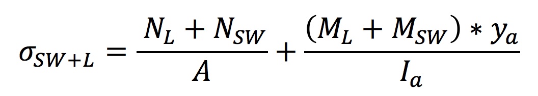
The equation used to calculate the stress of the laths in the third and fourth load cases is the following:
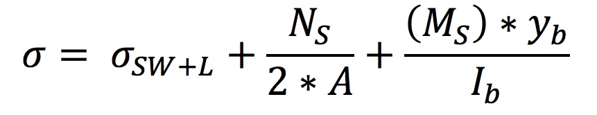 |
(7) |
where Ib is the moment of inertia of two connected laths, joined by a shear block, since these load cases are resisted by the shell as a whole once the shear blocks are in place, and yb is equal to 0.75m (perpendicular distance from the edge of a lath to the neutral axis of the combined laths and shear block).The area is twice as large in this instance because the stress is shared by two laths that are now connected.
Three load combinations were considered in this SAP2000 analysis. The first was purely the self-weight of the wooden grid and the loading needed to lift the laths to their required heights. The second combination included the snow load to the scenario and the last combination described the structure under wind loads as well. Table 3 shows that on average, the wind loads create a much larger total stress than the snow load.
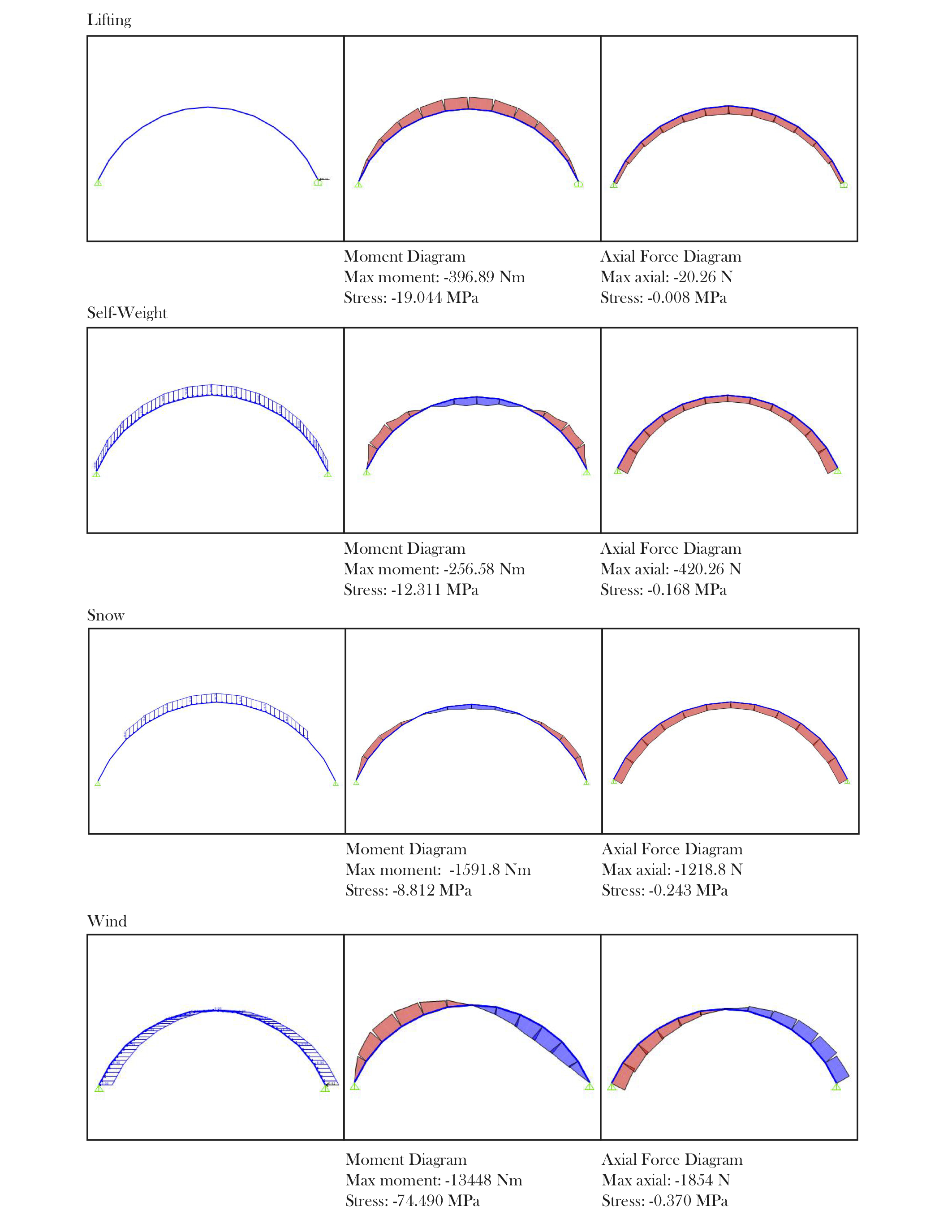 |
| Table 3: SAP2000 load diagrams and their contributions to normal stresses experienced by the shell |
Considering that the compressive strength of hemlock is 46.7 MPa, the maximum stresses created by the design loads (~25 MPa) is less than what this type of wood can resist [4]. Although the design wind loads surpass the strength of hemlock, in this analysis all the loads were supported by the strength of the strained wooden laths. These were designed to withstand compressive forces only, which is why additional bracing and shear blocks were purposefully placed in order to resist this disturbing wind load, ensuring the pavilion's structural safety.
The Mannheim Pavilion is impressive not only for its unique construction process, but also for its design durability despite the technological limits of the time in which it was envisaged and realized.
The Future of the Multihalle
Although the Mannheim Pavilion was originally meant to be a temporary structure, it is still standing today - approximately 37 years after it was completed. Unfortunately, the exhibition space is not currently in use and will remain closed to visitors until further notice due to structural maintenance. The pavilion is a significant achievement in its unusual shape and large span, as well as for its innovative use of timber to create a complex and flexible lattice previously unrivaled in timber engineering. Several other grid shells have been constructed since the completion of the Mannheim, including: the Japan Pavilion (2000, Hannover, Germany, Shigeru Ban and Frei Otto), the Weald and Downland Gridshell (2002, Singleton, England, Buro Happold and Edward Cullinan), and the Savill Gridshell (2006, Windsor, England, Buro Happold and Glen Howells Architects). These grid shells were constructed from different materials than the Mannheim, including cardboard tubes (Japan Pavilion), oak (Downland), and larch (Savill), and while both the Japan Pavilion and the Savill Gridshell achieve impressive spans, neither span total areas larger than the Mannheim [6].
[1] BNBF, Mannheim: A city at the crossroads of Germany, Study In Germany Website, Accessed on 13/11/2012.
[2] Davis, Richard G., (2006), "Bombing the European Axis Powers: A Historical Digest of the Combined Bomber Offensive," 1939-1945, Alabama: Air University Press.
[3] Happold, E., Liddell, W.I., (1975), Timber lattice roof for the Mannheim Budesgartenshau, The Structural Engineer, 53/3, March 1975, pp. 99-135.
[4] Happold, E., Liddell, W. I., (1976), Timber lattice roof for the Mannheim Bundesgartenschau, The Structural Engineer, No 7, Volume 54 (July 1976).
[5] IL 13: aa.vv., (1978), Multihalle Mannheim (Mitteilungen des Instituts für Leichte Flächentragwerke (IL) 13, Universität Stuttgart), Stuttgart, IL.
[6] Harris R et al, (2004), "The use of timber gridshells for long span structures," Proceedings of the 8th world conference on timber engineering WCTE 2004, Vol 1 (June 2004), pp. 99-104.
[7] Adriaenssens, S., Barnes, M., Harris, R., Williams, C., (2011), Design of a Wooden Strained Lattice Shell.
[8] Wendland, David, (1999), Model-based formfinding processes: Free forms in structural and architectural design, Universität Stuttgart, Institut für Darstellen und Gestalten.
[9] Bouhaya, L., (2010), Optimisation Structurelle des Gridshells, PhD Thesis Universite Paris-Est, Online.
[10] Timoshenko, S., (1936), Theory of Elastic Stability, McGraw Hill Book Company, New York and London.