


Balz House
Stetton, Germany
1980
Maximum Sphere Diameter: 7.8m
Heinz Isler, and Michael Balz
Social and Economic Context
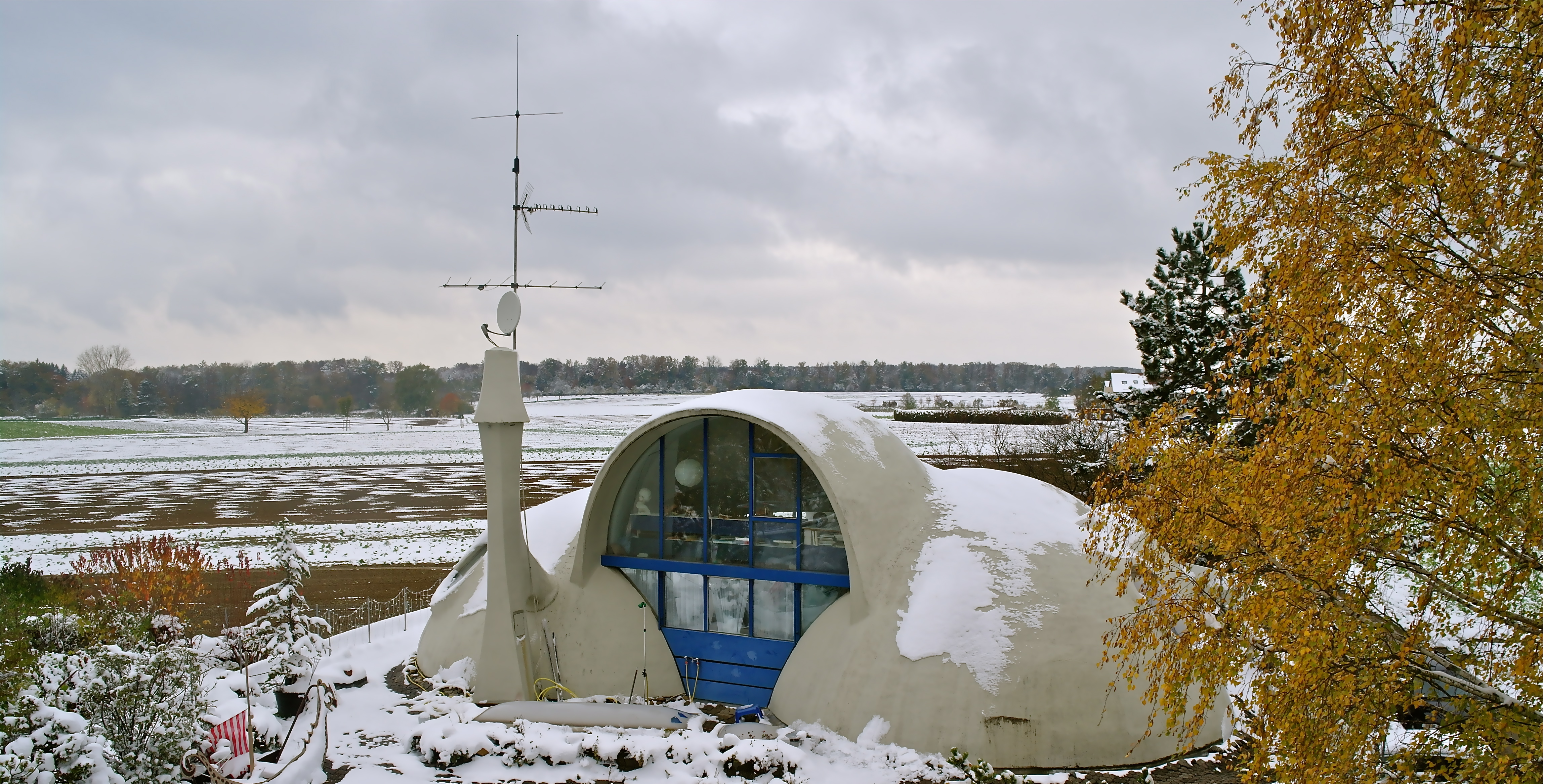 |
| Fig. 1: View of the outside of the Balz House, showing the domes which cover the upper living area. |
Completed by Michael Balz and Heinz Isler in the town of Stetten, Germany in 1980, the Balz House (Figure 1) is a pneumatic shell structure constructed in a period during which innovative structures were designed and built through the fusion of engineering and architecture. For the structure’s resident and architect Michael Balz, the house symbolized much more than an innovative structure – it served as a validation that organic forms could be built using pneumatic shells.
The 1970s not only saw increasing environmental and political awareness, and the advocacy of the organic movement, but also major Arab-Israeli conflicts and a worldwide energy crisis. In this crisis, major industrial countries faced large petroleum shortages, leading to an economic slowdown.1 The 1973 oil crisis and the 1979 energy crisis, both of which reduced the growth of major industrial economies,2 also led to the dramatic inflation of oil prices.3 These crises were caused by petroleum production peaks in the late 1960s - Germany reached its peak petroleum production around 1966, 7 years before the worldwide oil crisis.4 These events stimulated public awareness about the reliance on fossil fuels. In response to this growing awareness, a new party was introduced to the political scene. The Green Party, established in the 1960s, emphasized environmental awareness and the “green” movement- a movement towards the use of alternative sources of energy.5 In fact, in the late 1970s, the German branch of the Green Party received major public recognition, thus vaulting into the public eye.6
In addition, there was a major housing development policy introduced in Germany during that period. The “Urban Renewal and Town Development Act” aimed to meet housing demands by the 1990s. This characterized the beginning of large-scale developments with careful attention being paid to cultural heritage and preservation of buildings of historical interest. Through this movement, during which over 2.1 million new flats were built, there was great migration to the urban fringes, such as Stetten on the outskirts of Stuttgart, where the Balz House is located.7
Description of House
The Balz House is a single-family residence designed using a combination of curved surfaces and rectilinear forms. The upper part of the structure comprises 3 reinforced concrete domes, with radii ranging from 3.5 to 3.9 m and a thickness of 10 to 15 cm. These domes intersect one another to create a complex form with a clover shaped plan (Figure 2). This composite shape is located on an oval base with a maximum length of 17 m, forming the upper half of the house. A steep spiral staircase connects the more conventional rectangular rooms of the lower part of the house to the domes above (Figure 3).
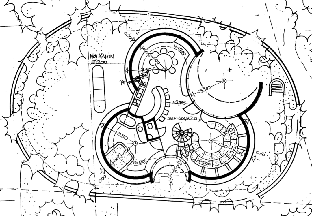 |
| Fig. 2: Photograph of the original plan of the house, showing the clover-shaped layout. Original Plan Courtesy: Michael Balz |
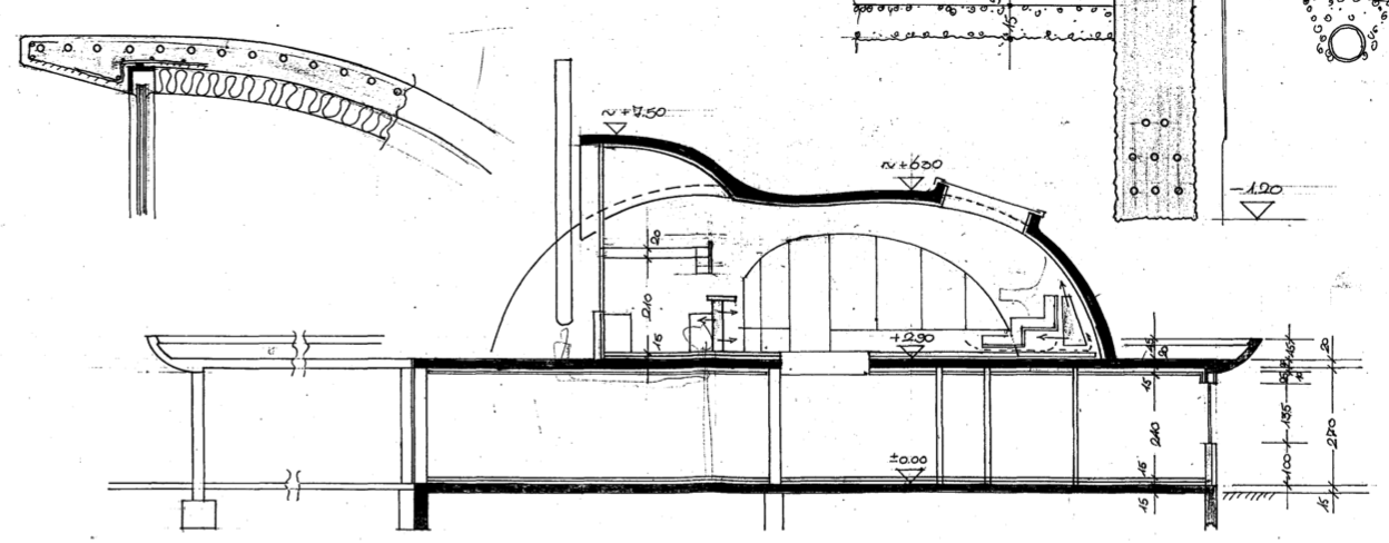 |
| Fig. 3: Section through the Balz House showing the lower rectangular rooms and upper curved space. Original Plan Courtesy: Michael Balz |
An office, children’s rooms, and a sculpture studio that is used by Balz’s wife are found in the lower part of the house, while a large living space is found in the upper part. The upper space comprises an open plan relaxation area with plush purple couches, a breakfast bar, kitchen, bedroom and bathroom alcove (Figure 4).8 The space is filled with handmade custom carved furniture produced by Balz to perfectly fit the curved form. Vertical sliding glass doors, a double-glazed roundel window and circular skylights illuminate the space, with the doors also allowing access to the viewing terrace just outside the house. Continuity is found between the living space and adjacent rooms, with the main bedroom containing a circular bed and a spherical bathroom. Even the telephone and television are in keeping with the curved purple and white interior. The lower part of the house, on the other hand, is not only filled with rectangular tables, chairs, and workspaces, but also has a contradicting green color scheme. This contradiction can be felt when one is within the house and gives a feeling of functionality to the lower studio area juxtaposed with the feeling of leisure in the upper living space.
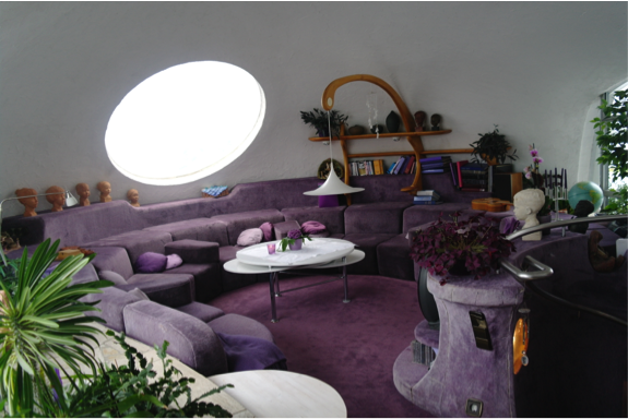 |
| Fig. 4: Curved purple and white interior of upper living space of the Balz House. |
The Form
Inspiration and Evolution
The inspiration behind the house’s unusual form, according to Michael Balz, was his mother. An avid sculptor, she once asked the young Balz why people could not simply “blow up houses”.9 To carry out this idea, Balz used a wooden carton and carved a hole in one side. A rubber balloon or PVC membrane was placed beneath this hole and was then blown up, such that a protruding surface was created through the carton. Gypsum (or plaster) was then cast on that inflated form to produce a plaster model of that shape. This shape is also known as a pneumatic shell shape, where pneumatic refers to its blown up construction. This method led to the development of the clover-like shape we see in the plan of the Balz House, “an absolute pneumatic, organic form which can be used for many ideas”, that is, adapted to create many different shapes and forms.9
Balz was keen to pursue this pneumatic form as not only was it cheap but the method allowed him to explore a variety of forms for the house. The open floor plan allowed for a variety of interior configurations, and the exterior form made it possible to cut out a number of openings. Thus at the IASS Colloquium in 1967, Balz approached Frei Otto to ask whether it would be possible to back up this form with calculations. While Otto said this would be extremely difficult, Heinz Isler, who was at the same colloquium, said that it was indeed possible.8 In fact, Isler had been conducting his own research on organic shapes and pneumatic form finding (‘bubble shells’).
Isler and Pneumatic Form Finding
Isler’s experiments with pneumatic forms date back to 1954 when he noticed the shape of the plumped-up pillow on his bed.8 The continuously curved surface of the pillow made him realize that physical models were the key to solving the problem of organic, free-form structures.
Isler’s simple yet elegant solution comprised a rectangular wooden frame placed on a wooden baseboard, with the latter having a small hole drilled into it. Isler then placed a pliable rubber sheet between the baseboard and the frame, with its perimeter restrained by clamping the two wooden boards together. A sealed flexible pipe and a hand pump could then be used to inflate the rubber membrane to produce a double-curved synclastic surface.8 This ‘technical pillow’ provided Isler with the opportunity to experiment with this form, and a similar apparatus was also used by Balz when designing his home.
Balz and Isler
In collaboration with Isler, Balz designed a theater complex in Stetten between 1976 and 1979, whose form was derived using a hanging membrane technique. The Balz House was constructed after this, adjacent to the theater complex. While the shapes at the theater complex differ from the pneumatic form of the Balz House, they nevertheless have an unconventional structural form. Thus, in a rather unusual move, the local planning authorities actually prescribed that Balz’s house resemble these adjacent shells in order to maintain a sense of uniformity in the area. Today however, as shells differ dramatically from the rectilinear forms most commonly used in residential housing today, these same regulations have prevented structures similar to the Balz House from being built.
Balz and Isler’s working relationship evolved into a firm friendship that was to last more than 20 years. Not only did they work on numerous projects together, but also frequently consulted each other when they were working on other projects. Balz recalls, “If somebody asks [Isler] which ideas he has, he often came to me and asked how I would do it”.9
In addition to pneumatic form finding, the two worked together on multiple projects involving concrete shells inspired by botanical shapes- another passion of Balz’s. This ties back to the architect’s belief that human beings themselves grow according to the laws of nature. He believes that human living spaces should thus be modeled on natural forms such as orchid blossoms. According to Balz, these organic building forms take into account human living needs much better than purely orthogonal forms.10
Derivation of Final Form
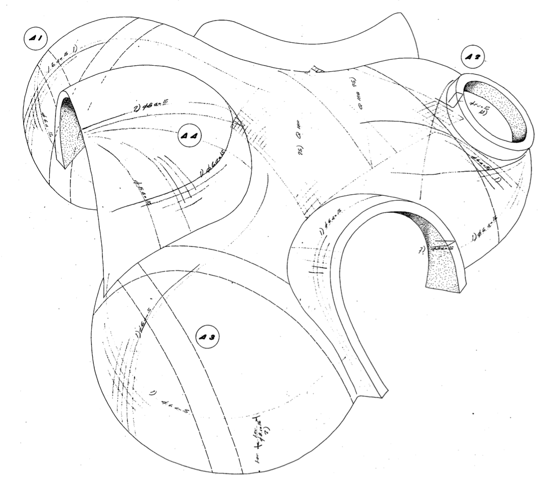
The final form of the Balz House was derived using the pneumatic form finding method described above. Balz first built a model at a scale of 1:20, with the construction occurring in parts. A wooden clover form was used as the restraining boundaries for the membrane, which was inflated using a bicycle pump. Balz first cast the basic shape on this form, and once this had set, he made openings in the surface under which he placed balloons and used these to produce the cantilevering forms. He finally added the upper cupola, which had been made independently of the basic form and cantilevers, to the model.9 This final form is shown in Figures 5 and 6.
 |
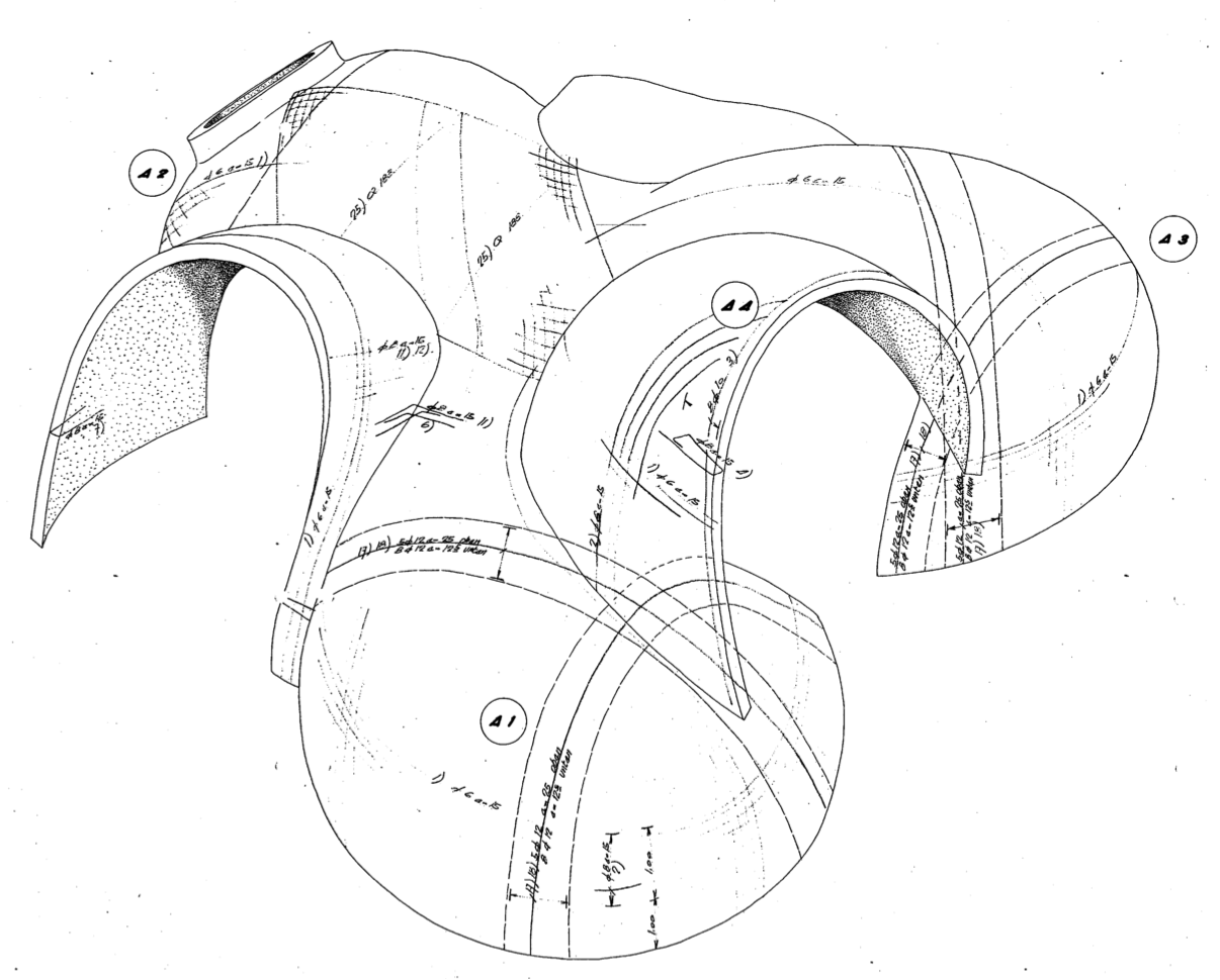 |
| Fig. 5: Final form of the Balz House (Model). Original Drawing Courtesy: Michael Balz. | Fig. 6: Final form of the Balz House (Model). Original Drawing Courtesy: Michael Balz. |
Strength Testing and Structural Integrity
The unusual form of the house makes it difficult to test the structure analytically, and thus the final form had to be physically tested for structural integrity. Deflections and stresses were induced in the scale models through the application of evenly distributed loads using a specially design wooden framework. The results were then measured through the use of electronic strain gauges located on the surface of the models.
The double-curved synclastic shape of these shells proved to be extremely stable- something that is attested to by the fact that after 30 years the building still has shown no signs of damage or cracks.11 As Balz observes, “as long as we have a cupola under compression, the house has no problem of cracking’’.9
Structural Analysis
As seen in Figure 2, the structure of the Balz House comprises 3 domes intersecting each other in order to create a complex form. As this form is rather difficult to analyze mathematically, it actually had to be physically tested for structural integrity using hanging weights. However, by breaking up the shell into components and approximating each component as a spherical dome, it is in fact possible to analyze the form mathematically. Assuming every dome is going to behave in roughly the same way, it is only necessary to analyze one of the domes.
The dome analyzed in this case was the one over the living room (Figure 4), which has a radius of 3.90 m, roll down angle of 82.6° and assumed pinned supports. This concrete dome was analyzed using analytical methods and the Finite Element Method in SAP2000.12
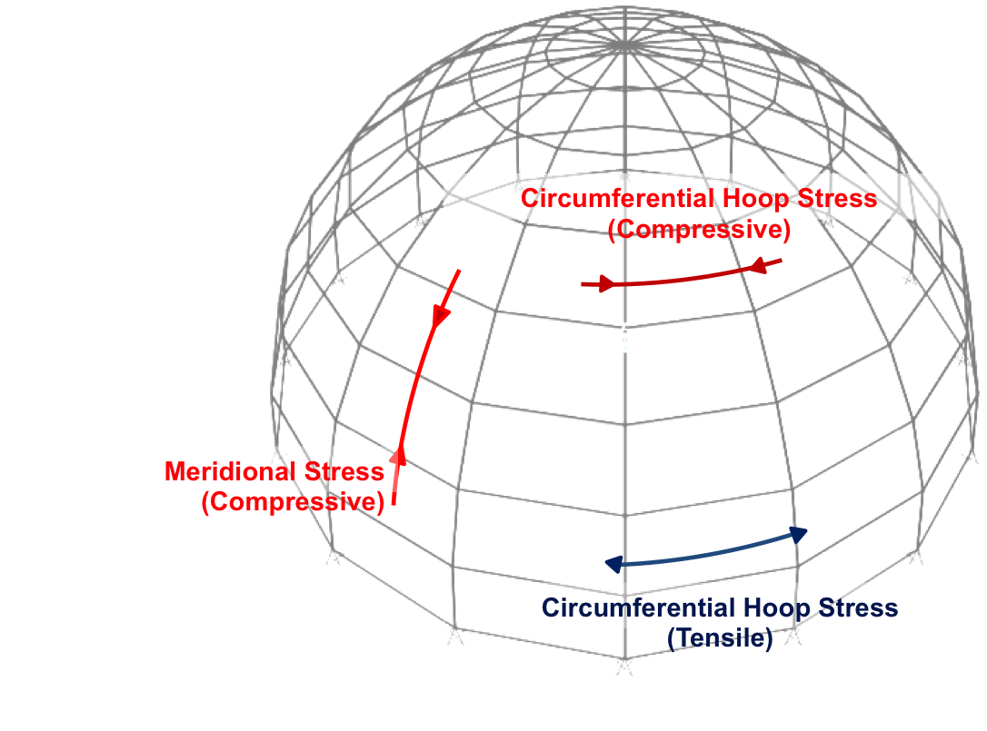 |
| Fig. 7: Hoop and Meridional Forces/Stresses in a Spherical Dome. |
Loads applied on the spherical dome generate bi-directional forces and stresses. These comprise hoop forces/stresses and meridional forces/stresses, as shown in Figure 7. The hoop and meridional forces can be calculated analytically using the following formulae:
Nϕ = -GR/(1 + cos ϕ) (1)13
Nθ = -GR(cos ϕ – 1/(1 + cos ϕ)) (2)13
Where:
- Nϕ = Meridional force
- Nθ = Hoop force
- G = Gravity load, which is this case is the density of the concrete multiplied by the thickness of the shell
- R = Radius of the shell (3.90 m)
- ϕ = Roll-down angle (Figure 8)
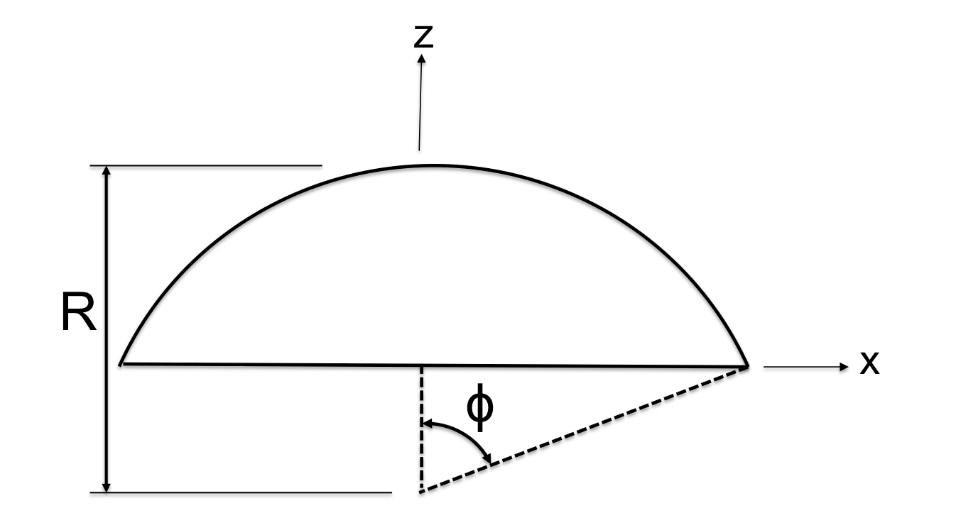 |
| Fig. 8: Schematic drawing showing radius and roll-down angle. |
Plotting these equations as functions of the roll down angle, graphs for meridional and hoop forces can be found, as shown in Figure 10. It can be seen that the meridional forces are always compressive, while the hoop force changes from compression to tension between the top and base of the dome . The two forces have the same value at the top of the dome (~7 kN per m length compression). While the meridional force gets gradually more compressive, with a maximum value of 12.33 kN/m at the base, the hoop force changes from compression to a maximum tensile force of 10.65 kN/m at the base, crossing from compression into tension (and hence being 0) at 52° from the vertical (Figure 9).
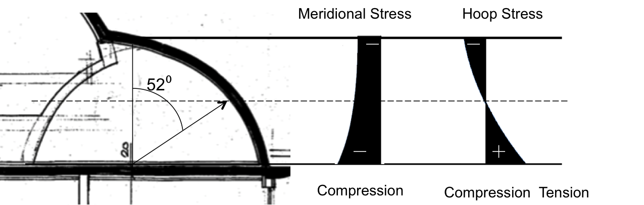 |
| Fig. 9: Distribution of hoop and meridional forces over selected dome of the Balz House. Adapted from original drawing provided by Michael Balz. |
Applying dead load only to the pinned dome, it is possible to compare the results from the SAP analysis with the analytical model. The force distribution obtained for the dead load case is shown in Figures 10 and 11, for the hoop and meridional forces respectively. From these distributions, it was found that the meridional force distribution is the same for both the analytical and SAP models, while the hoop force distribution varies. In the analytical model the force changes from ~7 kN/m (compression) to ~11 kN/m (tension). In the SAP model the force distribution changes from 7 kN/m (compression) to 6 kN/m (tension) before decreasing and becoming close to 0 near the supports. This difference is due to the fact that the analytical method assumed that only membrane forces existed in the shell, while SAP accounts for the horizontal reactions produced at the edges due to the pinned supports.
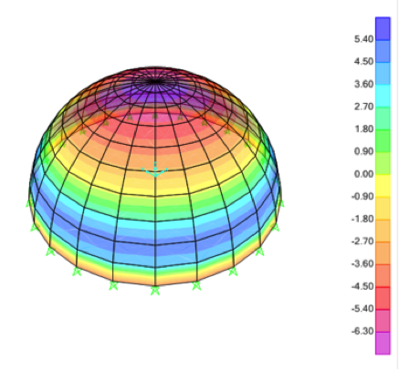 |
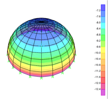 |
| Fig. 10: Hoop Force Distribution (kN/m). SAP2000. | Fig. 11: Meridional Force Distribution (kN/m). SAP2000. |
As houses are subject to external loads, it is important to understand their reaction to these. The Balz House is subject to snow and wind loads and so a combination of the dead and snow load, and the wind load have been tested for both pinned and fixed supports. The maximum and minimum stresses and bending moments (M) obtained for each case are listed in Table 1:
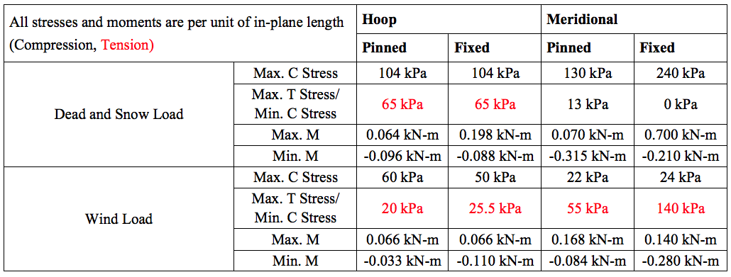 |
| Table. 1: Stresses and Bending Moments for a 3.9m span spherical dome with Pinned and Fixed Supports |
From Table 1 we see that the largest compressive stress (240 kPa) occurs under the dead and snow load in the meridional direction in the dome with fixed supports. The dome with fixed supports also experiences the largest tensile stress (140 kPa), again in the meridional direction, under the wind load. The maximum compressive stress is much smaller than the compressive strength of concrete, which is 20-40 MPa.14 The system is therefore structurally capable of coping with these compressive stresses. The maximum tensile stress is also less than the tensile strength of concrete, which is 2-5 MPa.14 However, reinforcement is still put into the structure in order to prevent cracking.
Examining the bending moment distributions, it was also found that the area of the dome with the greatest negative bending moment has the most bulging. The maximum negative moment of the pinned dome was found to exceed that of its fixed counterpart. Under the dead and snow load however, the dome with fixed supports was found to have the greatest positive bending moment at the supports, while the dome with pinned supports had no bending at the supports. This is due the fact that pinned supports have no moment.
This pattern is reversed under the wind load- the pinned dome was found to have the greater positive moment in the meridional direction (the moments in the hoop direction were the same), while the dome with the fixed supports was found to have the greater negative moment. This is most likely due to the fact that direction of the wind load resulted in a greater negative moment being generated at the supports.
Construction Process
The construction of the actual shell occurred over a formwork comprising transverse wooden frames. A woven steel net was then placed over this formwork, and a ‘rabbit’s net’, commonly used in Germany to carry the gypsum lengths, was placed on top (Figure 6). The first layer of concrete was then cast, with a second layer of steel and a layer of foam insulation being placed on top of it. Pipes serving as passive solar energy collectors were also placed on the inner layer of the shell. Using a crane, the second layer of concrete was poured on top to produce the final form (Figure 7).9
Balz recalls that the construction of this apparently complex form was actually relatively easy. The construction workers, who were Turkish, were extremely familiar with this cupola or domed form as it is very commonly used in their home country.9
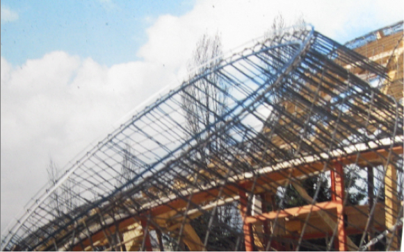 |
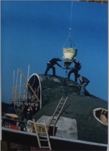 |
| Fig. 12: Wooden formwork and woven steel net used in the construction of the Balz House. Photo Courtesy: Michael Balz. | Fig. 13: Casting of final concrete layer using a crane. Photo Courtesy: Michael Balz. |
Energy Efficiency of Structure
Despite its unusual appearance, the design of the Balz House is actually extremely sophisticated and energy efficient. The amount of conventional heating required is minimal due to the innovative heating system present in the structure. Balz explained that the surface of the house absorbs heat from the sun, with surface temperatures reaching almost 45° C in the summer. Since heating is not required in the summer, the passive solar energy collectors transfer this heat underground for storage. This heat transfer occurs through the tubes and pipes embedded within the concrete, each with a diameter of 20 cm. The pipes circulate through the structure, with about 2500 m of piping in the surface, which continue into the earth, under the house and into the garden.9 In the winter, cold water enters the warming pump and is heated up by the outside soil temperature- this is then used to heat the base and walls of the house. Thus this system only requires electrical energy for the warming pump to heat the house. Balz also installed a fireplace in the house as a supplementary heating system, but said that they normally do not need it. Given the high price of electricity this heating system works out to be extremely cheap. In fact, during the heating period of 1980-1981, the heating cost of the system was found to be a mere 10 DM/m2.8
Its rounded form further augments the energy efficiency of this structure. This form makes it easier to absorb the solar energy, and the lack of angled corners prevents self-shading. The rounded form also limits the interior volume that requires heating and the surface area that requires insulation- thus further reducing the energy costs of the structure.8
Experience
Inside the house, one is overwhelmed by a feeling of coziness, which is exactly what Balz hoped to realize with this form. Balz wanted to limit orthogonal entities in the house and instead mimic the curved movement of the human form. The pneumatic method was found to lend itself well to such curved and rounded shapes. These shapes create not only an open plan but also a form that Balz suggests meets the psychological needs of its inhabitants. Residents feel protected within this space as the curved features and furniture enhance the feeling of being embraced, thereby providing a sense of continuity between the structure and its inhabitants.
Why Pneumatic Shell Houses are not Commonly Found
Although the Balz House was a great structural and aesthetic success, pneumatic shells are not common or preferred methods of home design and construction. While Balz believes that many people would like to live in such homes and wants to be able to provide people with them, zoning restrictions in Germany today have prevented such houses from being built. Furthermore, Isler’s methods, though apparently simple, are actually rather complex and require a high degree of precision.15 While Isler himself was very meticulous in methodology, the same is not necessarily true of all designers today and thus the complexity of these methods do not lend themselves to easy replication.
However, despite their applications being limited at a residential scale, these shells have the potential for industrial and large-scale applications. By producing them in a series, the fabrication cost decreases as the same formwork can be used repeatedly. This makes them an attractive option for low-cost emergency housing as they are cheap and can be prefabricated. Their lightweight nature also makes them easy to stack and transport.11 Therefore, although these pneumatic shell houses have not had much success on an individual scale, they have the potential to become an extremely attractive option for large-scale projects and should certainly not be overlooked.
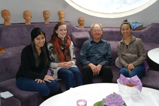 |
| Fig. 14: Webpage authors in Balz House with the architect, Michael Balz. From left to right: Anjali Mehrotra, Victoria Richardson, Michael Balz , and Sabrina Siu |
- D. Frum, How We Got Here: The 70’s, New York: Basic Books, pp. 292-293, 2000.
- “Total Energy – Annual Energy Review,” 2012. [Online]. Available: http://www.eia.gov/totalenergy/data/annual/index.cfm. [Accessed 4 December 2012].
- R. Barrell and O. Pomerantz, “Oil Prices and the World Economy,” in NIESR, vol. Dec, 2004.
- “Current World Oil Situation,” 2008. [Online], Available: http://www.planetforlife.com/oilcrisis/oilsituation.html. [Accessed 4 December 2012].
- “Green Party of the United States,” [Online], Available: http://www.gp.org/index.php. [Accessed 4 December 2012].
- “Green Parliamentary Group – German Bundestag,” [Online]. Available: https://www.gruene-bundestag.de/service-navigation/english_ID_2000025.html. [Accessed 4 December 2012].
- Federal Office for Building and Regional Planning. “Urban Development and Urban Policy in Germany. An Overview,” Bonn, pp. 49-50, 2000.
- J. Chilton, The Engineer’s Contribution to Contemporary Architecture: Heinz Isler, London: Thomas Telford Publishing, pp. 130-134, 2000.
- Private communication with Michael Balz (10/28/12).
- M. Balz and J. Guhring, “Botanic Shell Structures”, 2001.
- M. Balz, “Working with Heinz Isler,” in Journal of the International Association for Shell and Spatial Structures, pp. 155-160, 2011.
- CSI, SAP2000 Basic Analysis Reference, Berkeley: Version 7.0, 1998.
- D. Billington, Thin Shell Concrete Structures, New York: McGraw-Hill, 1982.
- “The Engineering ToolBox – Concrete Properties,” [Online]. Available: http://www.engineeringtoolbox.com/concrete-properties-d_1223.html. [Accessed 4 December 2012].
- J. Chilton, “Heinz Isler’s Infinite Spectrum: Form-Finding in Design,” in Architectural Design, vol. 80, pp. 64-71, 2010.